HDRI photography by Curtis Walker of some Urban Challenge competitors

The Challenges of the Urban
Challenge
The 2007 DARPA Urban Challenge (DUC07) presented its own
set of Challenges to 3rd St. R & D's staff.
The previous two DARPA Grand Challenge events took place over large geographical areas, and involved significant logistical challenges as well as technical scope challenges. The primary logistical challenges were locating and accessing remote mountaintop sites for location of voice and data network nodes, and transporting the physical facilities to those locations and servicing them over a period of months.
DUC07 took place in a small geographical area, but in some ways involved a larger technical/logistical scope. The same core requirements were in place, such as a large number of portable radios (300), a quantity of mobile radios (50), a multi-seat dispatch environment for 40+ command and control positions, microwave backhaul for public network connectivity, and vehicle tracking data from remote tracking nodes. In contrast to the previous events, no high ground existed on-site for location of communication facilities, and in the dense RF environment on the fringes of the LA area, wide coverage would be counterproductive. The proximity of Incumbent licensees would present interference issues to the temporary systems, and the temporary systems would have the probability of interfering with them. It was therefore necessary to limit the coverage scope of the temporary systems. High ground which was in proximity to the event site was highly congested (Quartzite Mountain) and had the near certainty of significant intermod and interference problems.
| In short, all "high ground" would
have to be brought in. That meant a primary portable tower for the Command
and Control Complex. It may be difficult for the reader to believe that
there could be radio coverage issues in an area this small, however the topology of the base was such that a critical portion
of the course was nearly 300' below the ground level of the Command
Complex. The event took place on Southern California
Logistics Airport (SCLA) in Victorville, California. Formerly George Air
Force Base, SCLA is undergoing radical re-configuration and construction,
and SCLA is an operating Airport so temporary tower
height would be limited. Another limiting factor to the portable
tower would be guying radius due to the small footprint of the
Command, Control, and Communications ( C3 ) compound. The high ground requirement could be satisfied easily with one of our AB1309 towers. The AB1309, however, should have a guying radius roughly equal to its deployed height. That would not be possible in the available space. A shallow guy radius would result in higher pulling force on the anchor points. It was decided to use our trailers as anchor points. Their combined weight is in excess of 100,000 pounds, which would secure the tower even with a guying radius half that normally required.
|
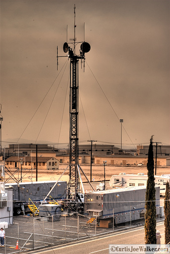 |
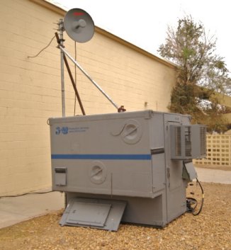
| Photo of our portion of the Command and Control Compound. Comm trailer is above and left of the tower, generator trailer is below and right, repeater shelter is left of the base of the tower. The corner of the Challenge Operations Center (COC) is visible at the left edge. |
Because of the reconstruction activity, many areas and most buildings in the majority of the old base are dark and have no Electrical utility service. Much of the electrical utility infrastructure that is left is derelict and will be torn out and rebuilt. There is essentially no modern subscriber telecom infrastructure in the area of SCLA that was used for DUC07, meaning that existing copper facilities were suspect or no longer terminated.
Local electrical utilities were unwilling to do a substantial electrical service installation that would only be used for a short (90 day) operational period, and most existing utility poles were in poor condition and unable to support the weight of transformers that would be required for the power service to support the C3 compound as well as the spectator area.
Fortunately, there were two old barracks buildings in reasonable proximity to the C3 compound which still had electrical service of significant capacity. That challenge would be to tap the building service to provide 800 amps of 120/208Y, and construct temporary support infrastructure for cabling to deliver that power to the compound. The support structures would need to withstand the late summer and early fall desert winds characteristic of the area, and allow installation of additional cabling in support of the television production of the event.
Also fortunately, Verizon had recently installed fiber capacity to the old base central office. No physical facilities existed to get service to the C3 Compound location, but connectivity could be provided with microwave equipment between the two locations.
Beginning in the Spring of 2007, 3rd St. R & D began planning a rapidly deployable support infrastructure system which could stay in place for four months, yet be completely gone and retrograded in less than one week at the conclusion of the event, "like we were never even there".
Power System
The two nearby barracks buildings each had 800 amp 480 volt services to them, and each had large switchgear panels which although old, were serviceable. Several options were considered, including having a local electrical contractor set a temporary meter and poles, and/or burying service lines. These two options were discarded due to price, appearance, and environmental concerns. The old base is suspected of ground contamination from years of insecticide usage, and deep digging or drilling was discouraged due to the possibility of exposing that contamination and opening a remediation issue of unknown magnitude. (You can readily smell insecticide in any remaining building in that area of the base, especially in the old base residential housing area)
It was known that in the middle of our deployment, there would also be a deployment of 5000 military personnel on the same area of the base for urban warfare training. Our installation would be required to be out of their way, self-contained, and present no contact hazard to personnel who were housed in the barracks.
The decision was made to tap the existing building switchgear buss, place a temporary 400A disconnect at the switchgear, and fly/swag temporary 4/0 camlock feeder from the barracks power room down the outer edge of the 3rd floor balcony of the barracks. Our thanks to JCustom Supply for their excellent cabling products and rapid delivery.
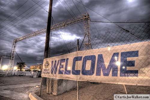 |
From the end of the barracks building, the feeder was flown from a messenger (support) cable to a 20' high truss bridge which crossed one of two streets and landed inside the fenced C3 compound. Once inside the fenced compound, it ran along the fence line to our generator/power distribution trailer. Our thanks to Tyler Truss Systems and Michael Gibson for their excellent products. |
At the trailer, after a 500' run from the barracks building, the 400A 480V delta service was stepped down onboard with a 250KVA transformer to 120/208Y to enter an automatic generator transfer switch and then route to the main distribution switchgear in the trailer. The custom-built trailer switchgear provided a 1000A variable trip main breaker and branch breakers ranging from 100 amps to 400 amps in capacity. The 400A branch breaker in the switchgear fed a 150KVA transformer which stepped back up to 480V for transmission over to the spectator tent area.
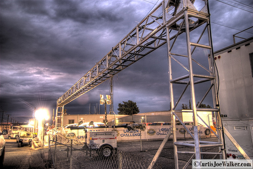 |
Enroute to the spectator tent, the tent 480V service crossed a pedestrian walkway and another street, requiring another truss bridge to support the feeder and more audio/video and network cabling. |
At the spectator tent, a portable shelter containing local 480V switchgear and two 75KVA step-down transformers was placed. One of these transformers was a shielded type which fed 200A Y120/208Y to the audio/video systems in the spectator tent. The other transformer fed 200A Y120/208 to the event lighting system in the tent consisting of PAR cans and moving lights. Lighting and Video systems provided by DAV Productions.
A third 45KVA transformer sourced from the shelter fed a sub panel which was dedicated to catering, registration and press tents, and user laptop power. (the requirement was for enough power for 100 laptops utilizing the hotspot in the tent)
Due to the widely disbursed services and sub panels, power system grounding was a critical consideration. The 480V delta configuration of the high-voltage system was chosen so that there were no ground runs of great length. At each step-down transformer, each derived system was grounded locally with a driven ground rod, or in the case of the main power trailer distribution, ground field. Care was taken to insure that audio/video and data circuits that had destinations in disbursed derived systems were linked with either fiber optic, or Ethernet that terminated in wireless access points to avoid ground loops.
Since the power origination at the barracks was over 1000' cable length away from the farthest point of use, circulating ground currents could have been a problem.
Communications System
The voice communications system was a repeat of the successful configurations used in previous DARPA Challenges, however the physical scope was greatly reduced.
Infrastructure
The system consisted of Motorola MTR2000 repeaters and satellite
receivers, Digitac Voting Comparators, and simplex base stations
consisting of CDM1550's and MTR2000's in base station configuration.
As mentioned earlier, it is difficult to believe that there could be coverage issues in such a small coverage area, but the topology dropped off suddenly in a critical area of the course. Full quieting performance could be realized at locations at street level 20 miles away with a walkie, but this area scarcely a mile away was badly impeded.
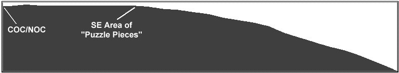
In this model, the right side is the bottom of the lowest portion of the course and is nearly 300 feet below ground level at the Challenge Operations Center where the main tower was located.
It was necessary to place a remote receiver site at a location overlooking this area, consisting of MTR2000 repeaters operating in receive-only mode. The area also presented problems to the vehicle tracking system, so a remote tracking system node was co-located with the radio receive site and both were linked back to the C3 compound with microwave.
Command and
Control
The Command Center was structured nearly
identically to the 2004 and 2005 events; with many observers, judges, and
vehicle monitors requiring access to the radio system.
As before, the Telex/Vega "CSoft" VoIP application provided the means to allow radio system access to 40+ users without cluttering the Challenge Operations Center and Network Operations Center with stray RF.
All computer station users within the COC, NOC, a remote Security Command Post, and a San Bernardino County Sheriff Command Post could access any radio channel, or combination of channels in the system. CSoft positions were also placed in both BSI's In-Car camera truck and NMT's primary video production truck to allow production personnel to stay apprised of vehicle progress on the course.
Six repeater channels and ten simplex channels were in operation. All channels, or subsets of the channels, were accessible to any radio or CSoft user depending on their requirements.
3rd St. R & D customized user interfaces with control surfaces specific to the system access needs of users or user groups.
|
|
|
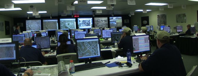
DARPA Challenge Operations Center with workstations and situational displays
|
|
|
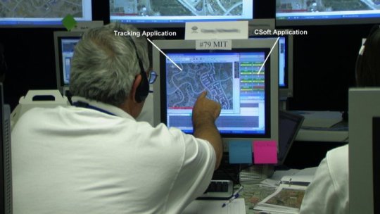
A DARPA Official monitoring the MIT entry moves his vehicle tracking situational display by touching the screen of his computer, while the CSoft communications application is in the background. A touch of the CSoft screen would bring it back to the front and allow the user to change channels and adjust volumes also by touch. Even while in the background, CSoft could be used on the selected channel. Custom built hand mic interfaces made transmitting with the CSoft application more instinctive, and provided better audio shaping and consistency than computer-style headset microphones. Users could choose between headphones or the speakers in the computers. Standard Motorola mobile hand mics were used with the interfaces. |
Radio Inventory
50 Motorola CDM1550 mobile radios were
installed in the 25 Control Vehicles and the 25 Live Traffic Vehicles,
while 310 walkies consisting of Motorola HT1250's and HT1550's were in the
hands of race officials and observers located all over the course and
starting line areas.
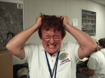
| Inventory
Management Char Harner, Project and Inventory Manager of 3rd St. R & D, exhibited her usual calm when dealing with the ever changing and dynamic inventory requirements of the event. |
 |
Vehicle Tracking System
Antennas and feed lines for the Government Owned "E-Stop" system were provided by 3rd St. R & D and located on our tower at the C3 complex. Both a tracking receive node and an E-Stop Master Transmitter were accommodated. As previously mentioned, an additional E-Stop tracking node was located at our remote receive site, and the real-time tracking data was transmitted back to the COC over our Adtran multiple T1 microwave system.
| Public and Internal Network | |
| As previously mentioned,
the lack of physical telecom facilities required Internet circuits to
be transmitted to the Network Operations Center via microwave. Again,
an Adtran TRACER multiple T1 microwave link handled 3 full rate Internet T1
circuits without any downtime which was related to the microwave
system.
For radio system site interconnect and tracking system data transmission, 3rd St. R & D relied once again on Adtran System components including, as above, TRACER Microwave, TSU600 multiplexers, and 1224R integrated switch/routers. |
|
|
Portable Tower System
|
|
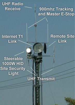 |
The primary tower located
at the C3 complex was very busy real estate, and fortunately the
AB-1309 tower is capable of lifting 1000 pounds of antenna load. 11 runs of 5/8" heliax added to the load of the antennas and other fixtures. 3rd St. R & D designed and implemented modifications to the legacy AB-1309 system to provide improved antenna mounting capability and the means to secure large numbers of feed lines, as well as mechanical modifications to improve the stability of the tower during erection and use. The remotely steerable Azimuth/Elevation heads make zeroing the Link paths very painless. |